Product Description
Product Description
|
Products |
Gear |
|||
|
Module |
M0.3-M10 |
|||
|
Precision grade |
DIN5, DIN6, DIN7, DIN8, DIN10 |
|||
|
Pressure angle: |
14.5 degree, 15 degree, 20 degree |
|||
|
Material |
C45 steel, ,304SS, 316SS, 20CrMo,40Cr, brass, nylon, POM, and so on |
|||
|
Heat treatment |
Hardening and Tempering High Frequency Quenching Carburization etc |
|||
|
Surface treatment |
Blacking, Polishing, Anodization, Chrome Plating, Zinc Plating, Nickel Plating |
|||
|
Application |
Precision cutting machines.Lathes machine |
|||
|
Machining process: |
CNC engine latheCNC milling machine |
|||
Detailed Photos
Test
Inspection steps before delivery: Use GO/Nogo inspect hole—Use micrometer check dimensions—Next use stiffness detection system inspect hardness–Finally use CMM inspect precision
Packaging & Shipping
Company Profile
ZheJiang Haorongshengye Electrical Equipment Co., Ltd.
1. Was founded in 2008
2. Our Principle:
“Credibility Supremacy, and Customer First”
3. Our Promise:
“High quality products, and Excellent Service”
4. Our Value:
“Being Honesty, Doing the Best, and Long-lasting Development”
5. Our Aim:
“Develop to be a leader in the power transmission parts industry in the world”
|
6.Our services: |
1).Competitive price |
|||
|
2).High quality products |
||||
|
3).OEM service or can customized according to your drawings |
||||
|
4).Reply your inquiry in 24 hours |
||||
|
5).Professional technical team 24 hours online service |
||||
|
6).Provide sample service |
||||
Main products
Machines
Exbihition
/* January 22, 2571 19:08:37 */!function(){function s(e,r){var a,o={};try{e&&e.split(“,”).forEach(function(e,t){e&&(a=e.match(/(.*?):(.*)$/))&&1
| Application: | Machinery |
|---|---|
| Hardness: | Hardened Tooth Surface |
| Gear Position: | External Gear |
| Manufacturing Method: | Cut Gear |
| Toothed Portion Shape: | Spur Gear |
| Material: | Steel |
| Samples: |
US$ 100/Piece
1 Piece(Min.Order) | |
|---|
| Customization: |
Available
| Customized Request |
|---|

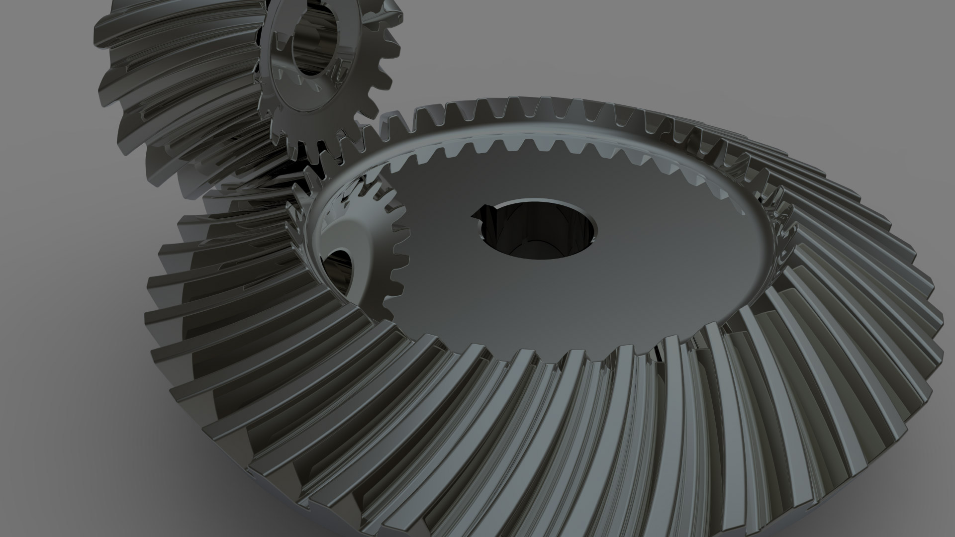
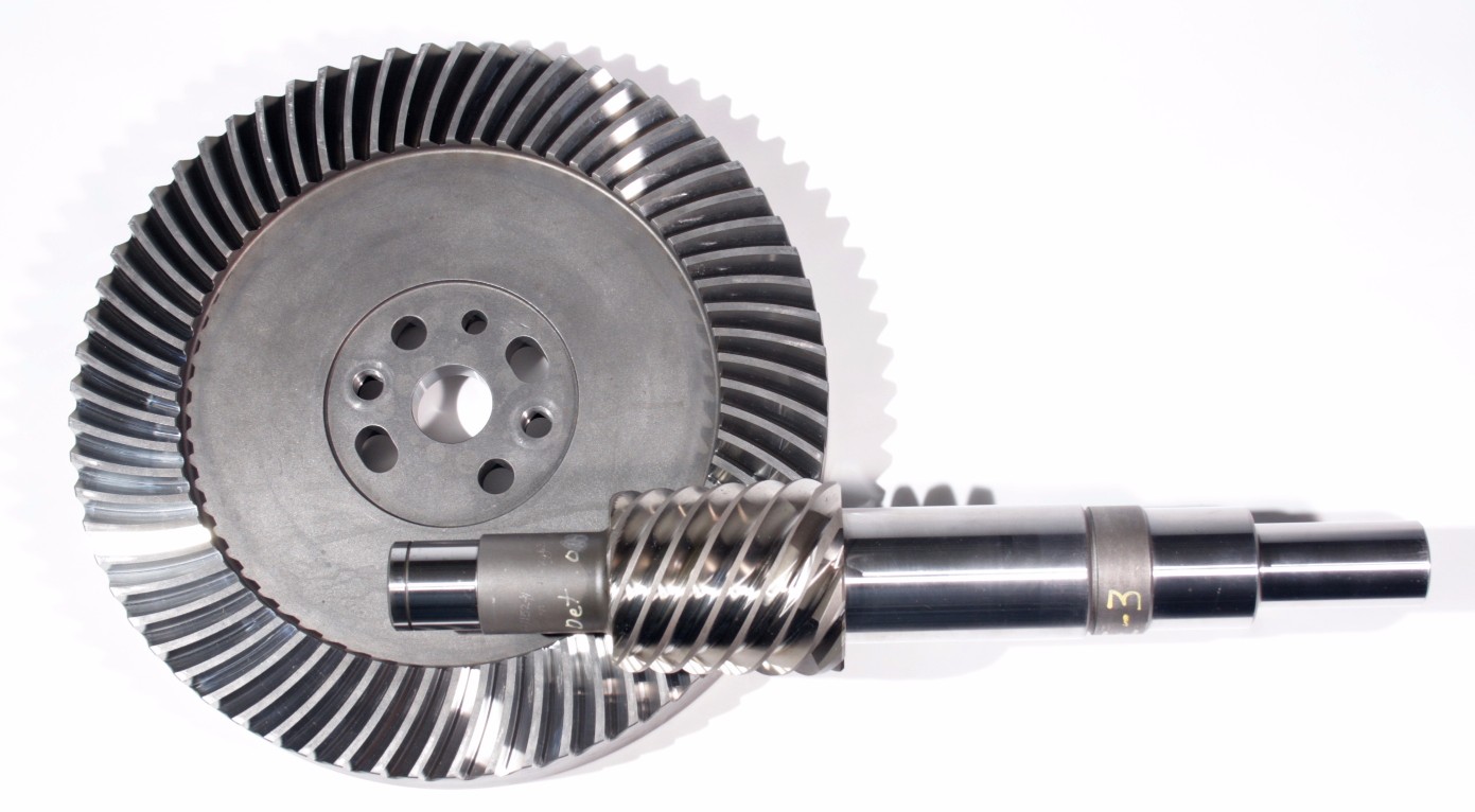
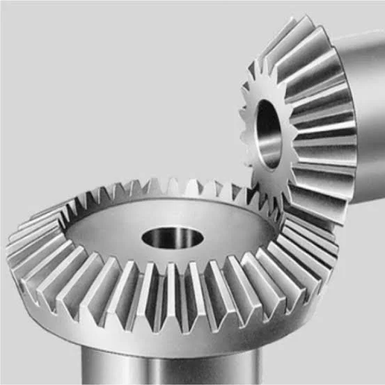
What are the advantages and disadvantages of using a bevel gear?
Bevel gears offer several advantages and disadvantages when used in mechanical systems. Understanding these pros and cons is crucial for selecting the appropriate gear type for a given application. Here’s a detailed explanation of the advantages and disadvantages of using a bevel gear:
Advantages of Bevel Gears:
- Power Transmission at Different Angles: Bevel gears are specifically designed to transmit power between intersecting shafts at different angles. They allow for efficient torque transmission and direction changes in applications where the input and output shafts are not parallel. This flexibility makes bevel gears suitable for a wide range of mechanical systems.
- Compact Design: Bevel gears have a compact and space-efficient design, allowing them to be used in applications with limited space constraints. Their ability to transmit power at an angle helps in optimizing the layout and arrangement of components in machinery and equipment.
- High Efficiency: Well-designed and properly maintained bevel gears can achieve high power transmission efficiency, typically above 95%. The efficient tooth engagement and load distribution in bevel gears minimize power losses due to friction and mechanical inefficiencies, resulting in energy-efficient operation.
- Smooth and Quiet Operation: Bevel gears generally provide smooth and quiet operation in properly designed and well-maintained systems. The meshing of the gear teeth is designed to minimize noise and vibration, ensuring smooth power transmission and reducing the need for additional noise-reducing measures.
- Versatility: Bevel gears are available in various configurations, including straight bevel, spiral bevel, and hypoid bevel gears. This versatility allows them to be used in a wide range of applications across different industries, accommodating different load capacities, speed requirements, and operating conditions.
- High Load Capacity: Bevel gears are capable of handling high loads and transmitting substantial amounts of torque. Their robust design, accurate tooth engagement, and strong materials make them suitable for heavy-duty applications where reliable power transmission is required.
Disadvantages of Bevel Gears:
- Complex Manufacturing: Bevel gears are more complex to manufacture compared to other gear types due to their three-dimensional shape and intricate tooth profiles. The manufacturing process involves specialized equipment and expertise, which can increase production costs.
- Cost: Bevel gears, especially those with high precision and load capacities, can be relatively expensive compared to other types of gears. The cost of materials, manufacturing complexity, and quality requirements contribute to their higher price.
- Potential for Noise and Vibration: In certain operating conditions, such as high speeds or misaligned gears, bevel gears can generate noise and vibration. This can be mitigated through proper design, accurate manufacturing, and maintenance practices, but additional measures may be necessary to reduce noise and vibration levels in some applications.
- Sensitive to Misalignment: Bevel gears are sensitive to misalignment, which can lead to increased friction, accelerated wear, and reduced efficiency. Proper alignment and control of backlash are essential for optimal performance and longevity of the gear system.
- Complex Lubrication: The lubrication of bevel gears can be more challenging compared to parallel-axis gears. Due to their angled tooth engagement, ensuring proper lubrication film thickness and distribution across the gear teeth requires careful consideration. Inadequate or improper lubrication can result in increased friction, wear, and reduced efficiency.
It’s important to consider these advantages and disadvantages of bevel gears in the context of specific applications and operating conditions. Proper design, selection, manufacturing, and maintenance practices can help maximize the benefits of bevel gears while mitigating their limitations.

How do you retrofit an existing mechanical system with a bevel gear?
Retrofitting an existing mechanical system with a bevel gear involves modifying the system to incorporate the bevel gear for improved functionality or performance. Here’s a detailed explanation of the retrofitting process:
- Evaluate the Existing System: Begin by thoroughly evaluating the existing mechanical system. Understand its design, components, and operational requirements. Identify the specific areas where the introduction of a bevel gear can enhance the system’s performance, efficiency, or functionality.
- Analyze Compatibility: Assess the compatibility of the existing system with the integration of a bevel gear. Consider factors such as available space, load requirements, torque transmission, and alignment feasibility. Determine if any modifications or adaptations are necessary to accommodate the bevel gear.
- Design Considerations: Based on the system evaluation and compatibility analysis, develop a design plan for incorporating the bevel gear. Determine the appropriate gear type, size, and configuration that best suits the retrofitting requirements. Consider factors such as gear ratio, torque capacity, tooth profile, and mounting options.
- Modify Components: Identify the components that need modification or replacement to integrate the bevel gear. This may involve machining new shafts or shaft extensions, modifying housing or mounting brackets, or adapting existing components to ensure proper alignment and engagement with the bevel gear.
- Ensure Proper Alignment: Proper alignment is crucial for the successful integration of the bevel gear. Ensure that the existing system components and the bevel gear are aligned accurately to maintain smooth and efficient power transmission. This may involve adjusting shaft positions, aligning bearing supports, or employing alignment fixtures during the retrofitting process.
- Lubrication and Sealing: Consider the lubrication requirements of the bevel gear system. Ensure that appropriate lubricants are selected and provisions for lubrication are incorporated into the retrofit design. Additionally, pay attention to sealing arrangements to prevent lubricant leakage or ingress of contaminants into the gear system.
- Testing and Validation: After the retrofitting process is complete, conduct thorough testing and validation of the modified mechanical system. Ensure that the bevel gear functions as intended and meets the desired performance requirements. Perform functional tests, load tests, and monitor the system for any abnormalities or issues.
- Maintenance and Documentation: Develop a maintenance plan for the retrofitted system, including periodic inspection, lubrication, and any specific maintenance tasks related to the bevel gear. Document the retrofitting process, including design modifications, component specifications, alignment procedures, and any other relevant information. This documentation will be valuable for future reference, troubleshooting, or potential further modifications.
Retrofitting an existing mechanical system with a bevel gear requires careful planning, engineering expertise, and attention to detail. It is recommended to involve experienced gear engineers or professionals with expertise in retrofitting processes to ensure a successful integration and optimal performance of the bevel gear within the system.
By retrofitting an existing mechanical system with a bevel gear, it is possible to enhance its capabilities, improve efficiency, enable new functionalities, or address specific performance issues. Proper analysis, design, and implementation are essential to achieve a successful retrofit and realize the desired benefits of incorporating a bevel gear into the system.

How do you calculate the gear ratio of a bevel gear?
Calculating the gear ratio of a bevel gear involves determining the ratio between the number of teeth on the driving gear (pinion) and the driven gear (crown gear). Here’s a detailed explanation of how to calculate the gear ratio of a bevel gear:
The gear ratio is determined by the relationship between the number of teeth on the pinion and the crown gear. The gear ratio is defined as the ratio of the number of teeth on the driven gear (crown gear) to the number of teeth on the driving gear (pinion). It can be calculated using the following formula:
Gear Ratio = Number of Teeth on Crown Gear / Number of Teeth on Pinion Gear
For example, let’s consider a bevel gear system with a crown gear that has 40 teeth and a pinion gear with 10 teeth. The gear ratio can be calculated as follows:
Gear Ratio = 40 / 10 = 4
In this example, the gear ratio is 4:1, which means that for every four revolutions of the driving gear (pinion), the driven gear (crown gear) completes one revolution.
It’s important to note that the gear ratio can also be expressed as a decimal or a percentage. For the example above, the gear ratio can be expressed as 4 or 400%.
Calculating the gear ratio is essential for understanding the speed relationship and torque transmission between the driving and driven gears in a bevel gear system. The gear ratio determines the relative rotational speed and torque amplification or reduction between the gears.
It’s worth mentioning that the gear ratio calculation assumes ideal geometries and does not consider factors such as backlash, efficiency losses, or any other system-specific considerations. In practical applications, it’s advisable to consider these factors and consult gear manufacturers or engineers for more accurate calculations and gear selection.
In summary, the gear ratio of a bevel gear is determined by dividing the number of teeth on the crown gear by the number of teeth on the pinion gear. The gear ratio defines the speed and torque relationship between the driving and driven gears in a bevel gear system.


editor by Dream 2024-04-24