Product Description
1) According to the different strength and performance, we choose the steel with strong compression;
2) Using Germany professional software and our professional engineers to design products with more reasonable size and better performance; 3) We can customize our products according to the needs of our customers,Therefore, the optimal performance of the gear can be exerted under different working conditions;
4) Quality assurance in every step to ensure product quality is controllable.
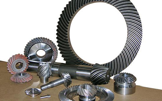
Product Paramenters
| DRIVEN GEAR |
NUMBER OF TEETH |
11 |
|
MODULE |
11.89 | |
|
LENTH |
282 | |
|
OUTER DIAMETER |
ø154 |
|
|
DIRECTION OF SPIRAL |
L |
|
|
ACCURACY OF SPLINE |
3-M16-7H | |
|
NUMBER OF SPLINE |
26 |
|
DRIVEN GEAR |
NUMBER OF TEETH |
37 |
|
OUTER DIAMETER |
ø434 |
|
|
DIAMETER OF INNER HOLE |
ø250 |
|
|
ACCURACY OF SCREW |
16-M16*1.5-7H | |
|
CENTER DISTANCE OF SCREW HOLE |
ø280 |
|
|
DIRECTION OF SPIRALR |
R |
Company Profiles
Our company,HangZhou CHINAMFG Gear co.,Ltd , specialized in Hypoid and spiral bevel gear used in Automotive industry, was foundeded in 1996, with registered capital 136,8 square meter, with building area of 72,000 square meters. More than 500 employees work in our company.
We own more than 560 high-precise machining equipments, 10 Klingelnberg Oerlikon gear production lines, 36 Gleason gear production lines, 5 forging production lines 2 german Aichilin and 5 CHINAMFG CHINAMFG advanced automatic continuous heat treatment production lines. With the introducing the advanced Oerlikon C50 and P65 measuring center, we enhence our technology level and improve our product quality a lot. We offer better quality and good after-sale service with low price, which insure the good reputation. With the concept of “for the people, by technology, creativity, for the society, transfering friendship, honest”, we are trying to provice the world-top level product.
Our aim is: CHINAMFG Gear,world class, Drive the world.
According to the different strength and performance, we choose the steel with strong compression;Using Germany professional software and our professional engineers to design products with more reasonable size and better performance;We can customize our products according to the needs of our customers,Therefore, the optimal performance of the gear can be exerted under different working conditions;Quality assurance in every step to ensure product quality is controllable.
Our company had full quality management system and had been certified by ISO9001:2000, QS-9000:1998, ISO/TS16949 , which insure the entrance of international market.
Certification & honors
Packaging & Shipping
Packaging Detail:standard package(carton ,wooden pallet).
Shipping:Support Sea freight. Accept FOB,EXW,FAS,DES.
Cooperative customers
HangZhou CHINAMFG Gear Co., Ltd. adheres to the concept of “people-oriented, prosper with science and technology; create high-quality products, contribute to the society; turn friendship, and contribute sincerely”, and will strive to create world automotive axle spiral bevel gear products.
1.Do you provide samples?
Yes,we can offer free sample but not pay the cost of freight.
2.What about OEM?
Yes,we can do OEM according to your requirements.
3.How about after-sales service?
We have excellent after-sales service if you have any quanlity problem,you can contact us anytime.
4.What about package?
Stardard package or customized package as requirements.
5.How to ensure the quanlity of the products?
We can provide raw meterial report,metallographic examination and the accuracy testing etc.
6.How long is your delivery time?
Genarally it is 4-7 days.If customized it will be take 20 days according to your quantity.
| Application: | Motor, Electric Cars, Motorcycle, Machinery, Marine, Agricultural Machinery, Car |
|---|---|
| Hardness: | Hardened Tooth Surface |
| Gear Position: | External Gear |
| Manufacturing Method: | Cast Gear |
| Toothed Portion Shape: | Herringbone Gear |
| Material: | Cast Steel |
| Samples: |
US$ 1175/Set
1 Set(Min.Order) | |
|---|
| Customization: |
Available
| Customized Request |
|---|
Can you provide examples of machinery that use bevel gears?
Bevel gears are widely used in various machinery and mechanical systems where torque transmission and direction changes are required. These gears are specifically designed to transmit power between intersecting shafts at different angles. Here are some examples of machinery and equipment that commonly use bevel gears:
- Automotive Industry: Bevel gears are extensively used in automotive applications. They can be found in different parts of vehicles, including the differential gear system, powertrain components, steering systems, and transfer cases. In the differential, bevel gears help distribute torque between the drive wheels while allowing them to rotate at different speeds during turns.
- Aerospace Industry: Bevel gears are utilized in various aerospace applications, such as aircraft engines, landing gear systems, and helicopter transmissions. They play a critical role in transferring power and changing the direction of rotation in these high-performance systems.
- Industrial Machinery: Bevel gears are commonly employed in industrial machinery and equipment. They are used in gearboxes, speed reducers, and power transmission systems. Examples include conveyors, mixers, pumps, packaging machinery, printing presses, and textile machinery. Bevel gears allow efficient power transmission and enable the machinery to operate at different speeds and directions as required by the specific application.
- Construction and Heavy Equipment: Bevel gears are found in construction equipment such as cranes, excavators, loaders, and bulldozers. They are integral components of the drivetrain systems, enabling the transfer of power and torque to the wheels or tracks, as well as facilitating steering and movement of the equipment.
- Marine Applications: Bevel gears are utilized in various marine applications, including propulsion systems, marine generators, winches, steering mechanisms, and anchor handling equipment. They help transmit power efficiently and withstand the challenging marine environment.
- Machine Tools: Bevel gears are employed in machine tools such as milling machines, lathes, and grinders. They are essential for transmitting power and facilitating the required speed and direction changes in these precision machining systems.
- Power Plants: Bevel gears are used in power generation facilities, including wind turbines, hydroelectric turbines, and steam turbines. They play a crucial role in converting the rotational motion of the turbine blades into electrical energy by transmitting torque to the generator.
- Mining and Material Handling: Bevel gears are commonly found in mining equipment, conveyor systems, and material handling machinery. They are used to transfer power and facilitate the movement of bulk materials, such as ores, coal, and aggregates.
These examples represent just a few of the many applications where bevel gears are utilized. Bevel gears offer versatility, efficiency, and reliability in transmitting power and changing direction in various mechanical systems across different industries.

How do you retrofit an existing mechanical system with a bevel gear?
Retrofitting an existing mechanical system with a bevel gear involves modifying the system to incorporate the bevel gear for improved functionality or performance. Here’s a detailed explanation of the retrofitting process:
- Evaluate the Existing System: Begin by thoroughly evaluating the existing mechanical system. Understand its design, components, and operational requirements. Identify the specific areas where the introduction of a bevel gear can enhance the system’s performance, efficiency, or functionality.
- Analyze Compatibility: Assess the compatibility of the existing system with the integration of a bevel gear. Consider factors such as available space, load requirements, torque transmission, and alignment feasibility. Determine if any modifications or adaptations are necessary to accommodate the bevel gear.
- Design Considerations: Based on the system evaluation and compatibility analysis, develop a design plan for incorporating the bevel gear. Determine the appropriate gear type, size, and configuration that best suits the retrofitting requirements. Consider factors such as gear ratio, torque capacity, tooth profile, and mounting options.
- Modify Components: Identify the components that need modification or replacement to integrate the bevel gear. This may involve machining new shafts or shaft extensions, modifying housing or mounting brackets, or adapting existing components to ensure proper alignment and engagement with the bevel gear.
- Ensure Proper Alignment: Proper alignment is crucial for the successful integration of the bevel gear. Ensure that the existing system components and the bevel gear are aligned accurately to maintain smooth and efficient power transmission. This may involve adjusting shaft positions, aligning bearing supports, or employing alignment fixtures during the retrofitting process.
- Lubrication and Sealing: Consider the lubrication requirements of the bevel gear system. Ensure that appropriate lubricants are selected and provisions for lubrication are incorporated into the retrofit design. Additionally, pay attention to sealing arrangements to prevent lubricant leakage or ingress of contaminants into the gear system.
- Testing and Validation: After the retrofitting process is complete, conduct thorough testing and validation of the modified mechanical system. Ensure that the bevel gear functions as intended and meets the desired performance requirements. Perform functional tests, load tests, and monitor the system for any abnormalities or issues.
- Maintenance and Documentation: Develop a maintenance plan for the retrofitted system, including periodic inspection, lubrication, and any specific maintenance tasks related to the bevel gear. Document the retrofitting process, including design modifications, component specifications, alignment procedures, and any other relevant information. This documentation will be valuable for future reference, troubleshooting, or potential further modifications.
Retrofitting an existing mechanical system with a bevel gear requires careful planning, engineering expertise, and attention to detail. It is recommended to involve experienced gear engineers or professionals with expertise in retrofitting processes to ensure a successful integration and optimal performance of the bevel gear within the system.
By retrofitting an existing mechanical system with a bevel gear, it is possible to enhance its capabilities, improve efficiency, enable new functionalities, or address specific performance issues. Proper analysis, design, and implementation are essential to achieve a successful retrofit and realize the desired benefits of incorporating a bevel gear into the system.

How do you calculate the gear ratio of a bevel gear?
Calculating the gear ratio of a bevel gear involves determining the ratio between the number of teeth on the driving gear (pinion) and the driven gear (crown gear). Here’s a detailed explanation of how to calculate the gear ratio of a bevel gear:
The gear ratio is determined by the relationship between the number of teeth on the pinion and the crown gear. The gear ratio is defined as the ratio of the number of teeth on the driven gear (crown gear) to the number of teeth on the driving gear (pinion). It can be calculated using the following formula:
Gear Ratio = Number of Teeth on Crown Gear / Number of Teeth on Pinion Gear
For example, let’s consider a bevel gear system with a crown gear that has 40 teeth and a pinion gear with 10 teeth. The gear ratio can be calculated as follows:
Gear Ratio = 40 / 10 = 4
In this example, the gear ratio is 4:1, which means that for every four revolutions of the driving gear (pinion), the driven gear (crown gear) completes one revolution.
It’s important to note that the gear ratio can also be expressed as a decimal or a percentage. For the example above, the gear ratio can be expressed as 4 or 400%.
Calculating the gear ratio is essential for understanding the speed relationship and torque transmission between the driving and driven gears in a bevel gear system. The gear ratio determines the relative rotational speed and torque amplification or reduction between the gears.
It’s worth mentioning that the gear ratio calculation assumes ideal geometries and does not consider factors such as backlash, efficiency losses, or any other system-specific considerations. In practical applications, it’s advisable to consider these factors and consult gear manufacturers or engineers for more accurate calculations and gear selection.
In summary, the gear ratio of a bevel gear is determined by dividing the number of teeth on the crown gear by the number of teeth on the pinion gear. The gear ratio defines the speed and torque relationship between the driving and driven gears in a bevel gear system.


editor by CX 2023-10-27