Product Description
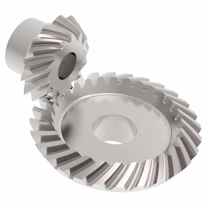
Wholesale Price Aluminum Stainless Steel Bevel Gear With High Precision
Gear transmission relies on the thrust between gear teeth to transmit motion and power, also known as meshing transmission. With this gradual meshing, helical gears operate much more smoothly and quietly than spur gears. Therefore, almost all automobile transmissions use helical gears.Since the teeth on the helical gear present a certain angle, the gears will be under a certain amount of stress when they mesh. Equipment using helical gears is equipped with bearings to withstand this pressure.
Product Description
| Product name | Helical Gear |
| Customized service | OEM, drawings or samples customize |
| Materials Available | Stainless Steel, Carbon Steel, S45C, SCM415, 20CrMoTi, 40Cr, Brass, SUS303/304, Bronze, Iron, Aluminum Alloy etc |
| Heat Treatment | Quenching & Tempering, Carburizing & Quenching, High-frequency Hardening, Carbonitriding…… |
| Surface Treatment | Conditioning, Carburizing and Quenching,Tempering ,High frequency quenching, Tempering, Blackening, QPQ, Cr-plating, Zn-plating, Ni-plating, Electroplate, Passivation, Picking, Plolishing, Lon-plating, Chemical vapor deposition(CVD), Physical vapour deposition(PVD)… |
| BORE | Finished bore, Pilot Bore, Special request |
| Processing Method | Molding, Shaving, Hobbing, Drilling, Tapping, Reaming, Manual Chamfering, Grinding etc |
| Pressure Angle | 20 Degree |
| Hardness | 55- 60HRC |
| Size | Customer Drawings & ISO standard |
| Package | Wooden Case/Container and pallet, or made-to-order |
| Certificate | ISO9001:2008 |
| Machining Process | Gear Hobbing, Gear Milling, Gear Shaping, Gear Broaching, Gear Shaving, Gear Grinding and Gear Lapping |
| Applications | Printing Equipment Industry, Laser Equipment Industry, Automated Assemblyline Industry, Woodening Industry, Packaging Equipment Industry, Logistics storage Machinery Industry, Robot Industry, Machine Tool Equipment Industry |
Company Profile
Packaging & Shipping
FAQ
| Main Markets? | North America, South America, Eastern Europe , West Europe , North Europe, South Europe, Asia |
| How to order? | * You send us drawing or sample |
| * We carry through project assessment | |
| * We give you our design for your confirmation | |
| * We make the sample and send it to you after you confirmed our design | |
| * You confirm the sample then place an order and pay us 30% deposit | |
| * We start producing | |
| * When the goods is done, you pay us the balance after you confirmed pictures or tracking numbers. | |
| * Trade is done, thank you!! |
If you are interested in our products, please tell us which materials, type, width, length u want.
/* January 22, 2571 19:08:37 */!function(){function s(e,r){var a,o={};try{e&&e.split(“,”).forEach(function(e,t){e&&(a=e.match(/(.*?):(.*)$/))&&1
| Application: | Motor, Electric Cars, Motorcycle, Machinery, Marine, Toy, Agricultural Machinery, Car, Textile Machinery |
|---|---|
| Hardness: | Hardened Tooth Surface |
| Gear Position: | External Gear |
| Manufacturing Method: | Rolling Gear |
| Toothed Portion Shape: | Spur Gear |
| Material: | Stainless Steel |
| Samples: |
US$ 10/Piece
1 Piece(Min.Order) | |
|---|
| Customization: |
Available
| Customized Request |
|---|

How do you prevent backlash and gear play in a bevel gear mechanism?
In a bevel gear mechanism, preventing backlash and gear play is essential for ensuring accurate and efficient power transmission. Backlash refers to the clearance or free movement between the mating teeth of gears, resulting in a brief loss of motion or a dead zone when changing direction. Here are some methods to prevent backlash and minimize gear play in a bevel gear mechanism:
- Precision Manufacturing: High-precision manufacturing processes are crucial for minimizing backlash and gear play in bevel gears. Accurate machining of gear teeth and precise control of tooth dimensions, profiles, and alignment help achieve tight meshing between the gears, reducing the clearance and backlash. Modern manufacturing techniques, such as CNC machining and gear grinding, can ensure the desired level of precision and minimize gear play.
- Proper Gear Design: The design of the bevel gears can influence the amount of backlash and gear play. An optimized gear design, including suitable tooth profiles, pressure angles, and tooth contact patterns, can help distribute the load evenly and minimize the clearance between the mating teeth. By carefully considering gear design parameters, designers can reduce backlash and improve gear meshing characteristics.
- Preload or Pre-Tension: Applying a preload or pre-tension to the bevel gears can help minimize backlash and gear play. This involves applying a slight force or tension to the gears, forcing them to maintain contact and reducing the clearance between the teeth. Preload can be achieved through various methods, such as using spring mechanisms, shimming, or adjusting the mounting position of the gears.
- Backlash Compensation: Backlash compensation methods aim to minimize the effects of backlash and gear play by introducing mechanisms or techniques that compensate for the clearance. One common approach is to use anti-backlash gears, which have special tooth profiles or arrangements that reduce or eliminate clearance between the mating teeth. Another method is to incorporate backlash compensation devices, such as spring-loaded mechanisms or adjustable shims, that actively reduce the backlash during operation.
- Tight Control of Tolerances: Maintaining tight tolerances during the manufacturing and assembly processes is critical for minimizing backlash and gear play. Close control of dimensions, alignment, and clearances ensures proper gear meshing and reduces the possibility of excessive play. Quality control measures, such as inspection, testing, and verification of gear dimensions, can help ensure that the gears meet the specified tolerances.
- Regular Maintenance: Regular maintenance practices, including inspection, lubrication, and adjustment, are essential for preventing and minimizing backlash and gear play over time. Periodic checks for wear, misalignment, and proper lubrication can help identify and rectify any issues that may contribute to increased backlash. Timely maintenance and replacement of worn or damaged gears can help maintain optimal gear meshing and minimize play.
By implementing these methods, it is possible to significantly reduce backlash and gear play in a bevel gear mechanism, resulting in improved accuracy, efficiency, and longevity of the gear system.

How do you retrofit an existing mechanical system with a bevel gear?
Retrofitting an existing mechanical system with a bevel gear involves modifying the system to incorporate the bevel gear for improved functionality or performance. Here’s a detailed explanation of the retrofitting process:
- Evaluate the Existing System: Begin by thoroughly evaluating the existing mechanical system. Understand its design, components, and operational requirements. Identify the specific areas where the introduction of a bevel gear can enhance the system’s performance, efficiency, or functionality.
- Analyze Compatibility: Assess the compatibility of the existing system with the integration of a bevel gear. Consider factors such as available space, load requirements, torque transmission, and alignment feasibility. Determine if any modifications or adaptations are necessary to accommodate the bevel gear.
- Design Considerations: Based on the system evaluation and compatibility analysis, develop a design plan for incorporating the bevel gear. Determine the appropriate gear type, size, and configuration that best suits the retrofitting requirements. Consider factors such as gear ratio, torque capacity, tooth profile, and mounting options.
- Modify Components: Identify the components that need modification or replacement to integrate the bevel gear. This may involve machining new shafts or shaft extensions, modifying housing or mounting brackets, or adapting existing components to ensure proper alignment and engagement with the bevel gear.
- Ensure Proper Alignment: Proper alignment is crucial for the successful integration of the bevel gear. Ensure that the existing system components and the bevel gear are aligned accurately to maintain smooth and efficient power transmission. This may involve adjusting shaft positions, aligning bearing supports, or employing alignment fixtures during the retrofitting process.
- Lubrication and Sealing: Consider the lubrication requirements of the bevel gear system. Ensure that appropriate lubricants are selected and provisions for lubrication are incorporated into the retrofit design. Additionally, pay attention to sealing arrangements to prevent lubricant leakage or ingress of contaminants into the gear system.
- Testing and Validation: After the retrofitting process is complete, conduct thorough testing and validation of the modified mechanical system. Ensure that the bevel gear functions as intended and meets the desired performance requirements. Perform functional tests, load tests, and monitor the system for any abnormalities or issues.
- Maintenance and Documentation: Develop a maintenance plan for the retrofitted system, including periodic inspection, lubrication, and any specific maintenance tasks related to the bevel gear. Document the retrofitting process, including design modifications, component specifications, alignment procedures, and any other relevant information. This documentation will be valuable for future reference, troubleshooting, or potential further modifications.
Retrofitting an existing mechanical system with a bevel gear requires careful planning, engineering expertise, and attention to detail. It is recommended to involve experienced gear engineers or professionals with expertise in retrofitting processes to ensure a successful integration and optimal performance of the bevel gear within the system.
By retrofitting an existing mechanical system with a bevel gear, it is possible to enhance its capabilities, improve efficiency, enable new functionalities, or address specific performance issues. Proper analysis, design, and implementation are essential to achieve a successful retrofit and realize the desired benefits of incorporating a bevel gear into the system.
What is the purpose of using bevel gears in right-angle drives?
Using bevel gears in right-angle drives serves several purposes and offers advantages in transmitting power efficiently and smoothly at a 90-degree angle. Here’s a detailed explanation of the purpose of using bevel gears in right-angle drives:
- Change in Direction: One of the primary purposes of using bevel gears in right-angle drives is to change the direction of rotational motion. Bevel gears are designed to transmit power between intersecting or non-parallel shafts, allowing the input shaft and output shaft to be oriented at a 90-degree angle. This is particularly useful in applications where the space or mechanical constraints require a change in direction, such as in automotive differentials or power transmission systems that require a compact design.
- Space Efficiency: Bevel gears offer a space-efficient solution for right-angle drives. Their compact design allows for effective power transmission in applications with limited space. By using bevel gears, the drive system can be designed to occupy a smaller footprint compared to other mechanisms, making them suitable for applications where space is a critical consideration.
- Torque Transmission: Bevel gears are capable of transmitting high torque loads, making them suitable for right-angle drives. The meshing of the gear teeth provides a strong and reliable connection, allowing for efficient power transmission even at a 90-degree angle. This makes bevel gears suitable for applications that require the transmission of substantial torque, such as in industrial machinery, agricultural equipment, and heavy-duty power transmission systems.
- Speed Adjustment: Bevel gears in right-angle drives enable speed adjustment between the input and output shafts. By selecting bevel gears with different tooth counts, the rotational speed can be adjusted according to the desired output requirements. This feature is beneficial in applications where different speeds are needed for specific operations or to match the requirements of the driven equipment.
- Versatility: Bevel gears offer versatility in right-angle drives. They can be designed with different tooth profiles, such as straight-cut, spiral, or zerol, to optimize performance based on factors like noise reduction, load capacity, and efficiency. Additionally, bevel gears can be manufactured from different materials, allowing them to withstand different environmental conditions and requirements.
- Smooth Operation: Bevel gears, especially spiral bevel gears, provide smooth and efficient operation in right-angle drives. The gradual engagement of the curved teeth reduces noise, vibration, and shock during gear meshing, resulting in quieter operation and improved overall system performance.
- Wide Range of Applications: Bevel gears find extensive applications in right-angle drives across various industries. They are commonly used in automotive differentials, marine propulsion systems, industrial machinery, robotics, aerospace systems, and more. The ability to transmit power at a 90-degree angle efficiently and reliably makes bevel gears suitable for a wide range of applications.
In summary, using bevel gears in right-angle drives offers benefits such as changing the direction of motion, space efficiency, torque transmission, speed adjustment, versatility, smooth operation, and suitability for a wide range of applications. These advantages make bevel gears a preferred choice in numerous industries and systems that require efficient and reliable power transmission at a 90-degree angle.


editor by CX 2024-04-02