Product Description
Product Specification:
| Title | LiuGong CLG855 ZL50C bevel gear 41C0002X1A |
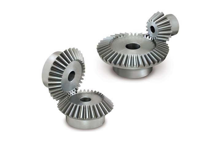
| Part Name | Bevel gear |
| Part No. | 41C0002X1A |
| Brand | LiuGong |
| Condition | Original/genuine parts |
| Net Weight | 160 KG |
| Packaging | Safety carton or wooden box |
| Delivery time | 2-5 working days |
Company Profile:
ZheJiang CHINAMFG Machinery Equipment Co., Ltd is 1 of the wholesaler, which specializes in providing LiuGong spare parts in China.
Our product range as following.
-
Parts for LiuGong wheel loader CLG835, ZL 30E, CLG842, ZL40B, ZL50C, ZL50CN, CLG856, CLG855, CLG862, CLG877 etc..
-
Parts for LiuGong excavator CLG205C, CLG915C, CLG916D, CLG920D/922D/923D/925D, CLG926LC etc..
-
Parts for LiuGong motor grader CLG414, CLG416, CLG418, CLG420.
-
Parts for LiuGong roller CLG612H, CLG614H, CLG618H, CLG614, CLG620 etc..
-
Parts for LiuGong compact wheel loader CLG816/816G, CLG820C, CLG836 etc..
-
Parts for LiuGong skid steer loader CLG365A, CLG375A
-
Parts for LiuGong backhoe loader CLG766, CLG777
-
Parts for LiuGong forklift CPC30, CPC35, CPCD30, CPCD 35 etc..
-
ZF transmission 4WG-200, 6WG-200, 4WG-180, 6WG-180.
-
PERMCO hydraulic pumps
We also have engine parts available for LiuGong machines. If you have any interest or enquiry of LiuGong parts, welcome to contact us.
Know more information, please visit to : http://liugongparts
Warehouse & spare parts pictures :
Packaging pictures
Our advantages & Services
1. Our company in the city where is liuGong factory/headquarter located, spare parts are taken from LiuGong warehouse directly.
2. Our company sell LiuGong genuine spare parts, complying with highest LiuGong performance standards.
3. Our company have own warehouse, which will guarantee you the high availability and short lead time (normal order 1-5 working days ).
4. Our team has rich experience in LiuGong spare parts.
5. Provide flexible pricing, offer discount and deferred payment for the wholesale buyers.
6. Accept payment by T/T and western union.
7. Accept terms of FOB, CIF, CPT ……etc.
If you want to know more infomation, please feel free to call or email us.
/* January 22, 2571 19:08:37 */!function(){function s(e,r){var a,o={};try{e&&e.split(“,”).forEach(function(e,t){e&&(a=e.match(/(.*?):(.*)$/))&&1
| After-sales Service: | Yes |
|---|---|
| Warranty: | Yes |
| Type: | Bevel Gear |
| Application: | Liugong Wheel Loader |
| Condition: | New |
| Original: | Yes |
What is the lifespan of a typical bevel gear?
The lifespan of a typical bevel gear can vary depending on several factors, including the quality of the gear, the operating conditions, maintenance practices, and the specific application. Here’s a detailed explanation:
Bevel gears, like any mechanical component, have a finite lifespan. The lifespan of a bevel gear is influenced by the following factors:
- Quality of the Gear: The quality of the gear itself is a significant factor in determining its lifespan. Bevel gears manufactured using high-quality materials and precise manufacturing processes tend to have longer lifespans. Gears made from durable materials and manufactured with tight tolerances and accurate tooth profiles are more resistant to wear and fatigue, resulting in extended lifespans.
- Operating Conditions: The operating conditions under which the bevel gear operates greatly affect its lifespan. Factors such as torque levels, rotational speed, temperature, and shock loads can impact the wear and fatigue characteristics of the gear. Gears subjected to high torque, high-speed rotation, excessive heat, or frequent heavy loads may experience accelerated wear and reduced lifespan compared to gears operating under milder conditions.
- Maintenance Practices: Proper maintenance practices can significantly extend the lifespan of a bevel gear. Regular inspection, lubrication, and preventive maintenance help identify and address potential issues before they escalate. Adequate lubrication, cleanliness, and alignment contribute to reducing wear, minimizing the risk of damage, and prolonging the gear’s lifespan. Neglecting maintenance or improper maintenance practices can lead to premature wear, failure, and reduced lifespan.
- Application Specifics: The specific application in which the bevel gear is used plays a vital role in determining its lifespan. Different applications impose varying loads, speeds, and operating conditions on the gear. Gears used in heavy-duty industrial applications, such as mining or heavy machinery, may experience more significant wear and have shorter lifespans compared to gears used in lighter-duty applications.
- Load Distribution: Proper load distribution among the gear teeth is critical for ensuring longevity. Evenly distributed loads help prevent localized wear and ensure that no individual teeth are subjected to excessive stress. Factors such as gear design, tooth profile, and accurate alignment influence load distribution and can impact the gear’s lifespan.
Due to the complex interplay of these factors, it is challenging to provide a specific lifespan for a typical bevel gear. However, with proper design, high-quality manufacturing, suitable operating conditions, regular maintenance, and appropriate load distribution, bevel gears can have a lifespan ranging from several thousand to tens of thousands of operating hours.
It is important to note that monitoring the gear’s condition, including wear patterns, tooth damage, and any signs of failure, is crucial for ensuring safe and reliable operation. When signs of wear or damage become significant or when the gear no longer meets the required performance criteria, replacement or refurbishment should be considered to maintain the overall system’s integrity and performance.
How do you address noise and vibration issues in a bevel gear system?
Noise and vibration issues in a bevel gear system can be disruptive, affect performance, and indicate potential problems. Addressing these issues involves identifying the root causes and implementing appropriate solutions. Here’s a detailed explanation:
When dealing with noise and vibration in a bevel gear system, the following steps can help address the issues:
- Analyze the System: Begin by analyzing the system to identify the specific sources of noise and vibration. This may involve conducting inspections, measurements, and tests to pinpoint the areas and components contributing to the problem. Common sources of noise and vibration in a bevel gear system include gear misalignment, improper meshing, inadequate lubrication, worn gears, and resonance effects.
- Check Gear Alignment: Proper gear alignment is crucial for minimizing noise and vibration. Misalignment can cause uneven loading, excessive wear, and increased noise. Ensure that the bevel gears are correctly aligned both axially and radially. This can involve adjusting the mounting position, shimming, or realigning the gears to achieve the specified alignment tolerances.
- Optimize Gear Meshing: Proper gear meshing is essential for reducing noise and vibration. Ensure that the gear teeth profiles, sizes, and surface qualities are suitable for the application. Improper tooth contact, such as excessive or insufficient contact, can lead to noise and vibration issues. Adjusting the gear tooth contact pattern, modifying gear profiles, or using anti-backlash gears can help optimize gear meshing and reduce noise and vibration.
- Ensure Adequate Lubrication: Proper lubrication is critical for minimizing friction, wear, and noise in a bevel gear system. Insufficient lubrication or using the wrong lubricant can lead to increased friction and noise generation. Check the lubrication system, ensure the correct lubricant type and viscosity are used, and verify that the gears are adequately lubricated. Regular lubricant analysis and maintenance can help maintain optimal lubrication conditions and reduce noise and vibration.
- Inspect and Replace Worn Gears: Worn or damaged gears can contribute to noise and vibration problems. Regularly inspect the gears for signs of wear, pitting, or tooth damage. If significant wear is detected, consider replacing the worn gears with new ones to restore proper gear meshing and reduce noise. Additionally, ensure that the gear materials are suitable for the application and provide adequate strength and durability.
- Address Resonance Effects: Resonance can amplify noise and vibration in a bevel gear system. Identify any resonant frequencies within the system and take steps to mitigate their effects. This may involve adjusting gear parameters, adding damping materials or structures, or altering the system’s natural frequencies to minimize resonance and associated noise and vibration.
Implementing these steps can help address noise and vibration issues in a bevel gear system. However, it is important to note that each system is unique, and the specific solutions may vary depending on the circumstances. Consulting with experts in gear design and vibration analysis can provide valuable insights and ensure effective resolution of noise and vibration problems.

How do you calculate the gear ratio of a bevel gear?
Calculating the gear ratio of a bevel gear involves determining the ratio between the number of teeth on the driving gear (pinion) and the driven gear (crown gear). Here’s a detailed explanation of how to calculate the gear ratio of a bevel gear:
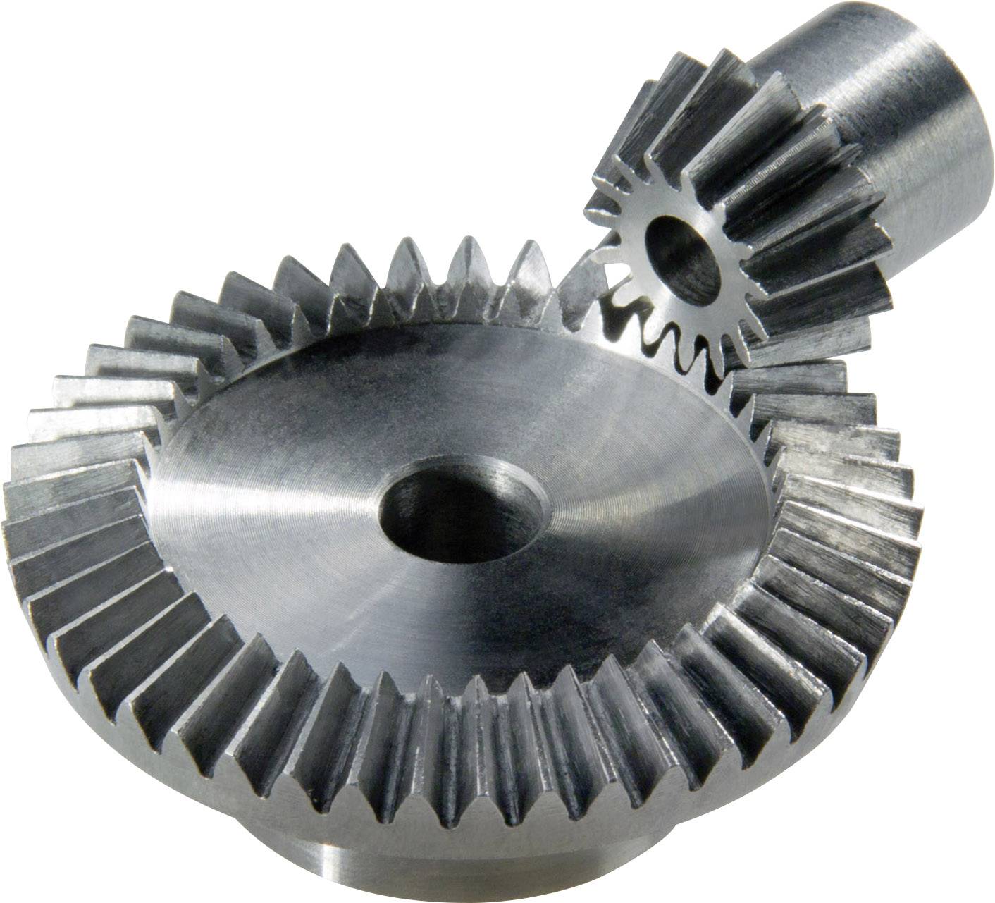
The gear ratio is determined by the relationship between the number of teeth on the pinion and the crown gear. The gear ratio is defined as the ratio of the number of teeth on the driven gear (crown gear) to the number of teeth on the driving gear (pinion). It can be calculated using the following formula:
Gear Ratio = Number of Teeth on Crown Gear / Number of Teeth on Pinion Gear
For example, let’s consider a bevel gear system with a crown gear that has 40 teeth and a pinion gear with 10 teeth. The gear ratio can be calculated as follows:
Gear Ratio = 40 / 10 = 4
In this example, the gear ratio is 4:1, which means that for every four revolutions of the driving gear (pinion), the driven gear (crown gear) completes one revolution.
It’s important to note that the gear ratio can also be expressed as a decimal or a percentage. For the example above, the gear ratio can be expressed as 4 or 400%.
Calculating the gear ratio is essential for understanding the speed relationship and torque transmission between the driving and driven gears in a bevel gear system. The gear ratio determines the relative rotational speed and torque amplification or reduction between the gears.
It’s worth mentioning that the gear ratio calculation assumes ideal geometries and does not consider factors such as backlash, efficiency losses, or any other system-specific considerations. In practical applications, it’s advisable to consider these factors and consult gear manufacturers or engineers for more accurate calculations and gear selection.
In summary, the gear ratio of a bevel gear is determined by dividing the number of teeth on the crown gear by the number of teeth on the pinion gear. The gear ratio defines the speed and torque relationship between the driving and driven gears in a bevel gear system.


editor by CX 2024-04-17