Product Description
Technical Features
The high degree of modularity is a design feature of SRC helical gearboxes range. It can be connected respectively with motors such as normal motor, brake motor, explosion-proof motor, frequency conversion motor, servo motor, IEC motor and so on. This kind of product is widely used in drive fields such as textile, foodstuff, ceramics packing, logistics, plastics and so on. It is possible to set up the version required using flanges or feet.
Products characteristics
SRC series helical gear units has more than 4 types. Power 0.12-4kw; Ratio 3.66-54; Torque max 120-500Nm. It can be connected (foot or flange) discretionary and use multi-mounting positions according to customers requirements.
Ground-hardened helical gears;
Modularity,can be combined in many forms;
Aluminium casing, light weight;
Gears in carbonize hard, durable;
Universal mounting;
Refined design,space effective and low noise
Structure feature
Model illuminate
|
1 |
Code for gear units series |
|
2 |
No F code means foot mounted.With F code B5 flange mounted.With Z code B14 flange mounted |
|
3 |
Specification code of gear units 01 |
|
4 |
I,II,III,B5 Output flange specification,default I not to write out is ok |
|
5 |
IEC: Input flange HS: shaft input |
|
6 |
Transmission ratio of gear units |
|
7 |
M1:Mounting position, default mounting position M1 not to write out is ok |
|
8 |
Position diagram for motor terminal box,default position o°(R) not to write out is ok |
|
9 |
No mark means without motor Model motor(poles of power) |
|
10 |
Voltage – frequency |
|
11 |
Coil in position for motor, default position S not to write out is ok |
4.2 Rotation speed n
n1 Gear units input speed
n2 Gear units output speed
If driven by the external gearing,1400r/min or lower rotation speed is suggested so as to optimize the working conditions and prolong the service life.Higher input rotation speed is permitted, but in this situation,the rated torque M2 will be reduced
4.5 Service factor fs
The effect of the driven machine on the gear unit is taken into account to a sufficient level of accuracy using the service factor fs. The service factor is determined according to the daily operation time and the starting frequency Z. Three load classifications are considered depending on the mass acceleration factor. You can read off the service factor applicable to your application in following figure. The service factor selected using this diagram must be less than or equal to the service factor as given in the performance parameter table.
* starting frequency Z: The cycles include all starting and braking procedures as well as change overs from low to high speed
SRC02..(HS) Performance parameter
|
kw |
Output speed |
Torque |
Speed ratio |
fs |
Model |
IEC |
|
0.12 |
16.7rpm |
204N.M |
54 |
1.0 |
SRC02 |
80B5/B14
|
Helical gearbox outline dimension heet
| Foot Code | U | V | V1 | V2 | V3 | W | X | X1 | Y | Z |
| B02 | 18 | 107.5 | 60 | – | 130 | 11 | 136 | 155 | 100 | 17 |
| M02 | 25 | 85 | – | 110 | 120 | 9 | 112 | 145 | 80 | 15 |
| M01 | 18 | 80 | – | 110 | 120 | 9 | 118 | 145 | 80 | 15 |
| B01 | 18 | 87 | 50 | 110 | – | 9 | 118 | 130 | 90 | 15 |
SRC helical gearbox with motor mounting position and terminal box orientation
Package
1 pc / carton,several cartons / wooden pallet
/* March 10, 2571 17:59:20 */!function(){function s(e,r){var a,o={};try{e&&e.split(“,”).forEach(function(e,t){e&&(a=e.match(/(.*?):(.*)$/))&&1
| Application: | Motor, Industry |
|---|---|
| Layout: | Coaxial |
| Hardness: | Hardened |
| Customization: |
Available
| Customized Request |
|---|
.shipping-cost-tm .tm-status-off{background: none;padding:0;color: #1470cc}
|
Shipping Cost:
Estimated freight per unit. |
about shipping cost and estimated delivery time. |
|---|
| Payment Method: |
|
|---|---|
|
Initial Payment Full Payment |
| Currency: | US$ |
|---|
| Return&refunds: | You can apply for a refund up to 30 days after receipt of the products. |
|---|

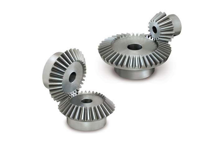
What is the lifespan of a typical bevel gear?
The lifespan of a typical bevel gear can vary depending on several factors, including the quality of the gear, the operating conditions, maintenance practices, and the specific application. Here’s a detailed explanation:
Bevel gears, like any mechanical component, have a finite lifespan. The lifespan of a bevel gear is influenced by the following factors:
- Quality of the Gear: The quality of the gear itself is a significant factor in determining its lifespan. Bevel gears manufactured using high-quality materials and precise manufacturing processes tend to have longer lifespans. Gears made from durable materials and manufactured with tight tolerances and accurate tooth profiles are more resistant to wear and fatigue, resulting in extended lifespans.
- Operating Conditions: The operating conditions under which the bevel gear operates greatly affect its lifespan. Factors such as torque levels, rotational speed, temperature, and shock loads can impact the wear and fatigue characteristics of the gear. Gears subjected to high torque, high-speed rotation, excessive heat, or frequent heavy loads may experience accelerated wear and reduced lifespan compared to gears operating under milder conditions.
- Maintenance Practices: Proper maintenance practices can significantly extend the lifespan of a bevel gear. Regular inspection, lubrication, and preventive maintenance help identify and address potential issues before they escalate. Adequate lubrication, cleanliness, and alignment contribute to reducing wear, minimizing the risk of damage, and prolonging the gear’s lifespan. Neglecting maintenance or improper maintenance practices can lead to premature wear, failure, and reduced lifespan.
- Application Specifics: The specific application in which the bevel gear is used plays a vital role in determining its lifespan. Different applications impose varying loads, speeds, and operating conditions on the gear. Gears used in heavy-duty industrial applications, such as mining or heavy machinery, may experience more significant wear and have shorter lifespans compared to gears used in lighter-duty applications.
- Load Distribution: Proper load distribution among the gear teeth is critical for ensuring longevity. Evenly distributed loads help prevent localized wear and ensure that no individual teeth are subjected to excessive stress. Factors such as gear design, tooth profile, and accurate alignment influence load distribution and can impact the gear’s lifespan.
Due to the complex interplay of these factors, it is challenging to provide a specific lifespan for a typical bevel gear. However, with proper design, high-quality manufacturing, suitable operating conditions, regular maintenance, and appropriate load distribution, bevel gears can have a lifespan ranging from several thousand to tens of thousands of operating hours.
It is important to note that monitoring the gear’s condition, including wear patterns, tooth damage, and any signs of failure, is crucial for ensuring safe and reliable operation. When signs of wear or damage become significant or when the gear no longer meets the required performance criteria, replacement or refurbishment should be considered to maintain the overall system’s integrity and performance.

What are the environmental considerations when using bevel gears?
When using bevel gears, there are several environmental considerations to keep in mind. These considerations encompass aspects such as material selection, lubrication, noise generation, and waste management. Here’s a detailed explanation:
1. Material Selection: The choice of materials for bevel gears can have environmental implications. Opting for environmentally friendly materials, such as recyclable or biodegradable materials, can help reduce the environmental impact. Additionally, selecting materials with low toxicity or hazardous properties contributes to safer handling and disposal practices.
2. Lubrication: Proper lubrication is essential for the efficient operation of bevel gears. However, the choice and use of lubricants can have environmental consequences. It is advisable to select lubricants that are environmentally friendly, such as biodegradable or non-toxic lubricants, to minimize the risk of contamination in case of leaks or spills. Additionally, implementing effective lubricant management practices, such as proper containment and recycling, helps reduce environmental pollution.
3. Noise Generation: Bevel gears can generate noise during operation, which can have environmental implications, especially in noise-sensitive areas or workplaces. Excessive noise can contribute to noise pollution and affect the well-being of individuals in the vicinity. Implementing noise reduction measures, such as using noise-dampening materials, optimizing gear design for quieter operation, and implementing proper maintenance practices, can help minimize noise pollution.
4. Energy Efficiency: Bevel gears are part of power transmission systems that consume energy. Considering energy efficiency in gear system design and operation can contribute to reduced energy consumption and lower environmental impact. This can be achieved by optimizing gear designs for higher efficiency, reducing friction losses through proper lubrication and surface treatments, and implementing efficient power transmission systems.
5. Waste Management: The manufacturing and maintenance processes involving bevel gears can generate waste materials, such as metal shavings, lubricant residues, or worn-out gears. Proper waste management practices, including recycling and disposal, are crucial to minimize the environmental impact. Recycling materials whenever possible and ensuring the proper disposal of hazardous or toxic waste materials are important considerations in reducing environmental pollution.
6. Life Cycle Assessment: Conducting a life cycle assessment (LCA) of bevel gears can provide a comprehensive understanding of their environmental impact. LCA takes into account the environmental implications associated with the entire life cycle of the gears, including raw material extraction, manufacturing, use, and end-of-life disposal. This assessment helps identify areas for improvement and guides decision-making towards more sustainable practices.
By considering these environmental factors, manufacturers, engineers, and users of bevel gears can make conscious choices to minimize the environmental impact associated with their production, operation, and disposal. Implementing sustainable practices and adhering to environmental regulations and standards contribute to a greener and more sustainable use of bevel gears.

How do you calculate the gear ratio of a bevel gear?
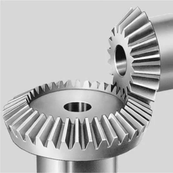
Calculating the gear ratio of a bevel gear involves determining the ratio between the number of teeth on the driving gear (pinion) and the driven gear (crown gear). Here’s a detailed explanation of how to calculate the gear ratio of a bevel gear:
The gear ratio is determined by the relationship between the number of teeth on the pinion and the crown gear. The gear ratio is defined as the ratio of the number of teeth on the driven gear (crown gear) to the number of teeth on the driving gear (pinion). It can be calculated using the following formula:
Gear Ratio = Number of Teeth on Crown Gear / Number of Teeth on Pinion Gear
For example, let’s consider a bevel gear system with a crown gear that has 40 teeth and a pinion gear with 10 teeth. The gear ratio can be calculated as follows:
Gear Ratio = 40 / 10 = 4
In this example, the gear ratio is 4:1, which means that for every four revolutions of the driving gear (pinion), the driven gear (crown gear) completes one revolution.
It’s important to note that the gear ratio can also be expressed as a decimal or a percentage. For the example above, the gear ratio can be expressed as 4 or 400%.
Calculating the gear ratio is essential for understanding the speed relationship and torque transmission between the driving and driven gears in a bevel gear system. The gear ratio determines the relative rotational speed and torque amplification or reduction between the gears.
It’s worth mentioning that the gear ratio calculation assumes ideal geometries and does not consider factors such as backlash, efficiency losses, or any other system-specific considerations. In practical applications, it’s advisable to consider these factors and consult gear manufacturers or engineers for more accurate calculations and gear selection.
In summary, the gear ratio of a bevel gear is determined by dividing the number of teeth on the crown gear by the number of teeth on the pinion gear. The gear ratio defines the speed and torque relationship between the driving and driven gears in a bevel gear system.


editor by CX 2024-01-11