Product Description
Material Options Most machinable materials, including:
-Aluminum(ADC12)
-Brass (H62)
-Bronze (ZCuAl10Fe3, ZCuSn12Ni2)
-Plastic (POM,PA66)
-Steel (Q235A, 45Cr, 20Cr, 20CrMnTi, 38CrMoAl)
-Stainless Steel (SUS201, SUS304, SUS316)
-Iron (HT200, HT250, QT450, QT500)
Surface Treatment :
-Black Coating
-Polishing
-Anodizing
-Chromium/Zinc/Nickel Plating
Machining Capabilities :
-Gear Cutting
-Precision Tuming
-Precision Milling
-CNC /Manual Mills
-Centerless Grinding
Quality and Inspection
-ISO 9001:2015 certificate
-CE certificate
-Certified Inspection and Test Equipment
| Application: | Motor, Electric Cars, Motorcycle, Machinery, Marine, Agricultural Machinery, Car |
|---|---|
| Hardness: | Hardened Tooth Surface |
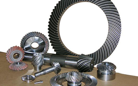
| Gear Position: | Internal Gear |
| Manufacturing Method: | Cast Gear |
| Toothed Portion Shape: | Bevel Wheel |
| Material: | Cast Steel |
| Customization: |
Available
| Customized Request |
|---|
Can you provide examples of machinery that use bevel gears?
Bevel gears are widely used in various machinery and mechanical systems where torque transmission and direction changes are required. These gears are specifically designed to transmit power between intersecting shafts at different angles. Here are some examples of machinery and equipment that commonly use bevel gears:
- Automotive Industry: Bevel gears are extensively used in automotive applications. They can be found in different parts of vehicles, including the differential gear system, powertrain components, steering systems, and transfer cases. In the differential, bevel gears help distribute torque between the drive wheels while allowing them to rotate at different speeds during turns.
- Aerospace Industry: Bevel gears are utilized in various aerospace applications, such as aircraft engines, landing gear systems, and helicopter transmissions. They play a critical role in transferring power and changing the direction of rotation in these high-performance systems.
- Industrial Machinery: Bevel gears are commonly employed in industrial machinery and equipment. They are used in gearboxes, speed reducers, and power transmission systems. Examples include conveyors, mixers, pumps, packaging machinery, printing presses, and textile machinery. Bevel gears allow efficient power transmission and enable the machinery to operate at different speeds and directions as required by the specific application.
- Construction and Heavy Equipment: Bevel gears are found in construction equipment such as cranes, excavators, loaders, and bulldozers. They are integral components of the drivetrain systems, enabling the transfer of power and torque to the wheels or tracks, as well as facilitating steering and movement of the equipment.
- Marine Applications: Bevel gears are utilized in various marine applications, including propulsion systems, marine generators, winches, steering mechanisms, and anchor handling equipment. They help transmit power efficiently and withstand the challenging marine environment.
- Machine Tools: Bevel gears are employed in machine tools such as milling machines, lathes, and grinders. They are essential for transmitting power and facilitating the required speed and direction changes in these precision machining systems.
- Power Plants: Bevel gears are used in power generation facilities, including wind turbines, hydroelectric turbines, and steam turbines. They play a crucial role in converting the rotational motion of the turbine blades into electrical energy by transmitting torque to the generator.
- Mining and Material Handling: Bevel gears are commonly found in mining equipment, conveyor systems, and material handling machinery. They are used to transfer power and facilitate the movement of bulk materials, such as ores, coal, and aggregates.
These examples represent just a few of the many applications where bevel gears are utilized. Bevel gears offer versatility, efficiency, and reliability in transmitting power and changing direction in various mechanical systems across different industries.

How do you ensure proper alignment when connecting a bevel gear?
Proper alignment is crucial when connecting a bevel gear to ensure efficient power transmission, smooth operation, and longevity of the gear system. Here’s a detailed explanation of how to ensure proper alignment:
When connecting a bevel gear, the following steps can help ensure proper alignment:
- Check Gear Specifications: Begin by reviewing the gear specifications provided by the manufacturer. This includes information about the gear’s design, tolerances, and alignment requirements. Understanding these specifications is essential for achieving the desired alignment.
- Prepare Mounting Surfaces: Ensure that the mounting surfaces for the gears, such as shafts or gearboxes, are clean, free from debris, and properly prepared. Any irregularities or surface defects can affect the alignment and lead to misalignment issues. Remove any burrs, nicks, or rough spots that could interfere with the proper seating of the gears.
- Use Alignment Tools: Alignment tools, such as dial indicators or laser alignment systems, can be helpful in achieving precise alignment. These tools allow for accurate measurement and adjustment of the gear’s position relative to the mating components. Follow the instructions provided with the alignment tools to set up and perform the alignment process correctly.
- Axial Alignment: Achieving proper axial alignment is crucial for bevel gears. The axial alignment refers to aligning the gear’s rotational axis parallel to the mating gear’s rotational axis. This ensures proper gear meshing and load distribution. Use alignment tools to measure and adjust the axial alignment, making necessary modifications to the gear’s position or shimming as required.
- Radial Alignment: Radial alignment involves aligning the gear’s rotational axis perpendicular to the mating gear’s rotational axis. Proper radial alignment helps prevent side loads, excessive wear, and noise generation. Use alignment tools to measure and adjust the radial alignment, ensuring that the gear’s position is properly adjusted or shimmed to achieve the desired alignment.
- Verify Tooth Contact Pattern: After aligning the gears, it is important to verify the tooth contact pattern. The tooth contact pattern should be evenly distributed across the gear tooth surfaces to ensure proper load sharing and minimize wear. Conduct a visual inspection or use specialized tools, such as gear marking compounds, to check and adjust the tooth contact pattern if necessary.
By following these steps and using appropriate alignment tools, you can ensure proper alignment when connecting a bevel gear. Proper alignment promotes efficient power transmission, minimizes wear, reduces noise, and extends the lifespan of the gear system.
It is worth noting that each gear system may have specific alignment requirements and considerations. Consult the gear manufacturer’s guidelines and best practices, as well as seek the expertise of experienced engineers, to ensure the proper alignment of bevel gears in your specific application.

How do you choose the right size bevel gear for your application?
Choosing the right size bevel gear for your application involves considering various factors such as load requirements, speed ratios, tooth geometry, and material selection. Here’s a detailed explanation of the considerations involved in selecting the right size bevel gear:
- Load Requirements: Determine the torque and power requirements of your application. This involves understanding the load conditions, including the magnitude and direction of the applied forces. Calculate the required torque capacity of the bevel gear based on the expected load and operating conditions.
- Speed Ratios: Determine the desired speed ratios between the input and output shafts. Bevel gears are often used to transmit rotational motion at different speeds. Calculate the required gear ratio to achieve the desired speed output and select bevel gears with appropriate tooth counts to achieve the desired ratio.
- Tooth Geometry: Consider the tooth geometry of the bevel gears. Straight bevel gears and spiral bevel gears have different tooth profiles and engagement characteristics. Evaluate the impact of tooth geometry on factors such as noise, vibration, smoothness of operation, and load-carrying capacity. Choose the tooth profile that best suits the specific requirements of your application.
- Material Selection: Consider the material properties of the bevel gears. The material should have sufficient strength, durability, and resistance to wear and fatigue. Common materials for bevel gears include steel alloys, cast iron, and non-ferrous alloys. The material selection should be based on factors such as load requirements, operating conditions (e.g., temperature, moisture), and any specific industry standards or regulations.
- Size and Dimensions: Consider the physical size and dimensions of the bevel gears. Evaluate the available space and clearance in your application to ensure proper fit and alignment of the gears. Consider factors such as the gear diameter, face width, and shaft bore diameter. Ensure that the selected bevel gears can be mounted and meshed correctly with the mating gears.
- Manufacturing and Cost Considerations: Take into account any specific manufacturing considerations or constraints. Consider factors such as gear manufacturing methods (e.g., cutting, shaping, forging), availability of standard gear sizes or custom gear manufacturing options, and associated costs. Balance the performance requirements of your application with the available budget and manufacturing feasibility.
It is often beneficial to consult with gear manufacturers, engineers, or industry experts to ensure the proper selection of bevel gears for your specific application. They can provide guidance on gear design, material selection, and performance analysis to help you choose the right size bevel gear that meets your requirements.
In summary, choosing the right size bevel gear involves considering factors such as load requirements, speed ratios, tooth geometry, material selection, size and dimensions, and manufacturing considerations. Taking into account these factors will help ensure that the selected bevel gear is suitable for your application, providing reliable and efficient power transmission.


editor by CX 2023-11-30